
Our Products
What are Flanges?
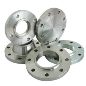
Flanges are used to connect valves, pipes, pumps and other equipment to make a pipework system. Typically flanges are welded or threaded, and two flanges are connected together by bolting them with gaskets to provide a seal that provides easy access to the piping system. These Flanges are available in various types such as slip on flanges, weld neck flanges, blind flanges, and socket weld flanges, etc. Below we have explained the various types of flanges used in the piping systems depends on their sizes other factors.
Types of Flanges:
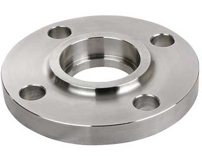
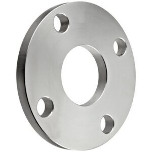
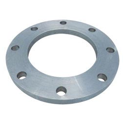
1. Slip On Flangs
Slip on Flange Is fundamentally a ring placed over the end of the pipe, with a flange face extending from the end of the pipe by sufficient distance to apply a welded bead to the inner diameter. As the name suggests these flanges slip over a pipe and hence known as Slip On Flanges. A slip-on flange is also known as SO flange. It’s a kind of flange that are slightly bigger than the pipe and slides over the pipe, with internal design. Since the inner dimension of the flange is slightly bigger than the external dimension of the pipe, the top and bottom of the flange can be connected directly to equipment or pipe by fillet welding the SO flange. It is used to insert the pipe into the flange’s inner hole. Slip-on pipe flanges are used with a raised or flat face. Slip-On Flanges are a suitable choice for low-pressure applications. Slip on flange is excessively utilized in many fluid pipelines.
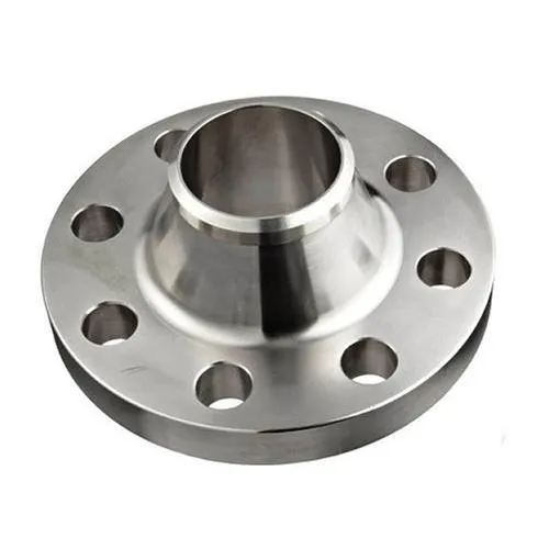
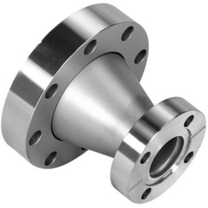
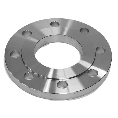
2. Weld Neck Flanges
Weld Neck Flange also known as a tapered hub flange or high-hub flange. Weld neck flange (WN flange) has a neck that can move the pipe tension, thereby reducing the pressure gathered in the bottom of the flange. It is compatible with the pipelines which operate at high or low temperatures and withstand high pressure. Welding Neck Flanges are effortlessly identifiable at the long tapered end, which slowly passes through the wall thickness from a pipe or fitting. The long tapered hub provides significant shielding for use in multiple applications involving high pressure, sub-zero and/or high temperatures. A weld neck flange comprises of a circular fitting with a protruding edge around circumference. Weld Neck Flange has been used successfully at pressures up to 5,000 psi.
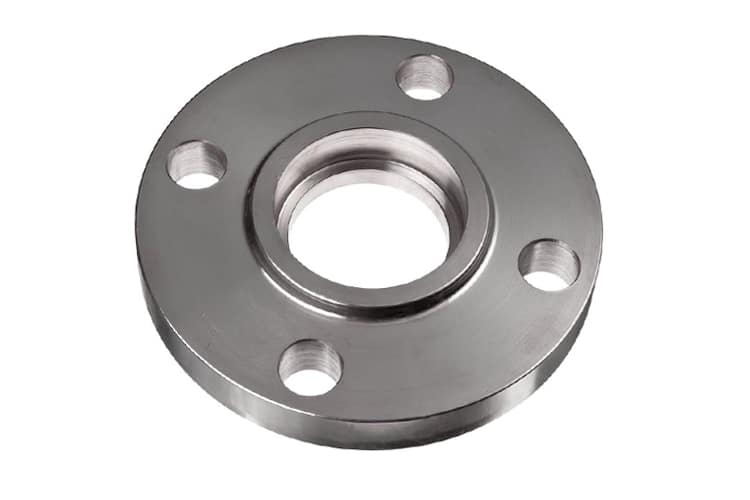
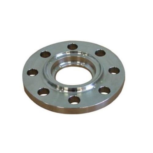
3. Socket Weld Flanges
The Socket weld flanges are only connected on the outside by one fillet weld, and are often not advised for critical services. These are mostly used for the small-bore lines. Their static strength is equivalent to Slip On flanges, but their fatigue strength is 50 percent higher than double-welded Slip On flanges. For this type of flanges, the thickness of the connecting pipe should be defined to ensure proper bore length. Before welding, a gap must be formed in the socket weld flange between the flange or fit and the pipe. The objective of a Socket Weld’s bottom clearance is generally to minimize the residual pressure at the weld root that could occur during weld metal solidification. The socket weld flange’s drawback is the right space, which must be made. The crack between the pipe and the flange can cause corrosion problems by corrosive products, and mostly in stainless steel pipe systems. This flange is not allowed in some processes. Also for this flange, that principle must always be welded first by a pipe and then simply by a fitting.
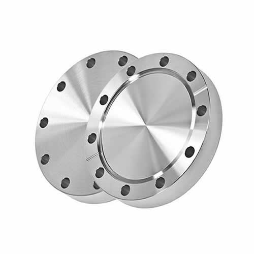
4. Blind Flanges
Blind Flanges are produced without a bore and are utilized to blank off the ends of pipes, valves and pressure vessel openings. From the point of view of internal pressure and bolt loading, the most overstressed flange types are blind flanges, especially in bigger sizes. Nevertheless, most of these pressures are bending types near the center and, as there is no standardized inner diameter, these flanges are ideal for higher pressure temperature systems. The function of these flanges is to obstruct a segment of the pipe or a nozzle on a vessel that is not in use. The nozzle will often be blanked off with a blind flange for pressure checks in a plant or simply because the consumer does not need all the nozzles that were provided on the tank.
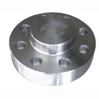
5. Reducing Flanges
Reducing flanges is designed for when the size of the pipe changes. The flange (dimensions) predominantly matching the larger pipe size (NPT) but having a smaller bore matching the smaller pipe size (NPT). These flanges generally come in neck flanges that are blind, slip-on, threaded, and weld. They are available in all pressure classes and offer an excellent alternative to connecting two different pipe sizes. This type of flange should not be used if an unexpected change, such as at a pump, would cause unnecessary turbulence.
Designed for use in piping system of changing diameters. A reduction flange consists of a one-specified diameter flange with a separate and smaller diameter bore. The flange will have measurements of the greater pipe size except for the bore and hub dimensions. Reducing flanges are attached by welding, gluing or clamping flanges of the same size supplied with different connecting pieces.
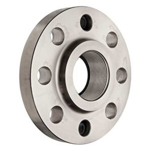
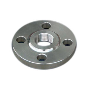
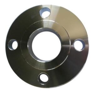
6. Threaded Flanges
Threaded flanges look nearly identical to Slip-On flanges but the key difference is that the threaded flange has been bored out to match the inside diameter of a particular pipe. Threaded flange is a type of flange that has taper pipe threads in its bore conforming to ASME B1.20.1 and can be used in piping systems where welding flange onto the pipe is not possible, such as highly explosive areas where welding can develop potential risk. The threaded flange is fixed onto a pipe that has additional threads to the taper pipe Galvanized and cast-iron piping is commonly used with threaded flanges. In very high pressure systems and for small diameters, threaded flanges can be used and their main benefit is that they can be installed without welding.
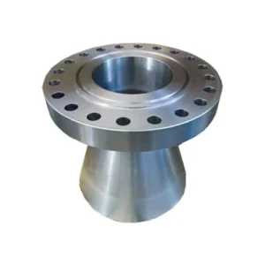
7. Expander Flange
An expander flange, referred to as EXPF, represents a welded neck flange but the hub extends to a larger size (one or two sizes). If you have limited space or just need to connect to a wider pipe diameter, it provides a convenient place for equipment, pumps, and vents. The compact size saves space compared with a reducer-welding neck flange which can eliminate the use of flange and reducer. Expander flanges are also considered a cost-effective alternative to using the reducer-welding neck flange separately. Pressure ratings and dimensions comply with ANSI / ASME B16.5. Expander flange has a raised face. Installing the Expander Flange requires a single butt-weld.
8. Spade and Ring Spacer Flange
Spade and Ring Spacer Flange are essentially similar to Spectacle Blinds, with the exception that they are not both connected. Spades and spacers are used in systems where maintenance isn’t often required or they are often used in large pipe size applications. Spades can weigh hundreds of pounds depending on the flange sizes and the Stress levels. In order to avoid additional weight, the flange connection is specifically chosen not for the Spectacle Blind, but for 2 separate parts. High maintenance of the pipe system can be a major reason to temporarily replace the Ring Spacer with a spade. perimeter and an opening in the center the size of the pipe that is supposed to be welded onto the loose flange. There are loose flange types are fit to in use elbows, valves and almost any type of pipeline component.
9. High Hub Blind Flanges
The High Hub Blind Flange is being used to seal the ends of the pipe structures. It’s a kind of circular plate with no center hold but with all the right bolt holes. The high hub blind flange is available in a variety of sizes and materials and is used to provide a constructive closer at the ends of pipes, valves or nozzles. When sealed, this flange allows you to easily access the line. Sometimes the high hub blind flange can be specially built or machined to match the nominal size of the pipe to which the reduction is made. This reduction could be a reduction in threads or a reduction in welds. Often high hub blind flanges are supplied with NPT fittings which allow the installation of pressure test connections. Considering factors such as internal pressure and bolt loading, high hub blind flanges are the most stressed of all types of flanges, particularly in the larger sizes.
10. Screwed Flanges
Screwed flange are also known as a Threaded Flange, and it is having a thread inside the flange bore which fits on the pipe with matching male thread on the pipe and these flanges are mostly used in utility services such as air and water. Screwed flange is often used for requirements on small diameter, high pressure. Screwed flanges with a hub have issued requirements ranging from 1/2′′ to 24′′. Pressure class: Class 150 to Class 2,500, PN 2.5 to PN 250 and Facing: RF / RTJ
Screwed flanges are threaded in a bore that matches the pipe’s external thread. Screwed flanges are used with external threaded pipes. The advantage of these flanges is that they can be mounted without welding.
11. Flat Face
In the same plane, the Flat Face flange has a gasket surface as the face of the bolting circle. Applications using flat facial flanges are often those in which casting is made of the mating flange or flanged fitting. A flat steel flange is quoted as a flange which is machined flat and does not have a ridge-like elevated face or ring type joint flange. The loose flat flange flat surface allows full contact between the gasket and the entire matting surface.
Flat face flanges should never be bolted onto an elevated face flange. ASME B31.1 states that the elevated face on the carbon steel flange must be removed when connecting flat face cast iron flanges to carbon steel flanges and that a full face gasket is required. The flange face form refers to all applications in which cast iron and other brittle materials are used to produce equipment and valves. For “Flat Face” flanges only Full Face Gaskets are to be used. This ensures that the two mating flanges are in full and equal contact.
12. Raised Face Flanges
The Raised Face flange is the most common type used in process plant applications, and can be easily identified. It is called an uplifted face because the surfaces of the gasket are raised above the face of the bolting circle. For all forged steel flanges like machinery and valves, this form of flange mask is commonly used. A wide combination of gasket designs can be used in the Raised face flanges. These combinations can also include Flat ring sheets and spiral wound and double jacketed type’s metallic components.
The Raised Face Flanges are used to concentrate more pressure on a smaller area of the gasket and thus increase the joint’s pressure containment capability. The Bolt holes are found in the outer ring region for those flanges. The “Move” adjustment between the heights of the two rings helps greater force to be applied to the gasket region, thereby creating a stronger seal when a gasket is attached and the bolts are mounted and torqued. Based on the pressure class, the flange face is either 1/16″ or 1/4″ ANSI 300 and under have a 1/16″ face raised, and ANSI 400 and higher have a 1/4″ face raised.

13. Male & Female Flanges
Male & Female Flanges are a kind of flange that wants to fit one another. One flange face in these variations has a region which stretches beyond the usual flange face. This flange is named The Man. The mating flange or the other flange, on the other side, will have a similar depression machined into its nose. This mating flange is called the Woman flange
The flanges must be aligned with this form too. Each facial flange has a region that stretches beyond the normal face of the flange (Male). The other flange or mating flange has a corresponding depression (Female) machined into the face of it.
The female faces are supposed to be 3/16-inch long, the male face are supposed to be 1/4-inch wide and each end flat. The female face’s exterior diameter serves to find and maintain the gauze. There are in fact 2 versions; the Medium M&F Flanges and the Wide M&F Flanges.
Male and female flanges have improved sealing abilities, more reliable positioning and specific compression of sealing material, use of other, more effective sealing material and advanced sealing material (O-rings).
Different Types of International Standard for flanges:
1. ASME B16.5 Flanges
The ASME B16.5 standard covers NPS 1/2 through NPS 24 Metric / Inch steel pipe flanges and flanged fittings in pressure class 150 to class 2500. This includes levels of pressure-temperature, components, lengths, tolerances, naming, measuring and methods of designating openings for flanged fittings and pipe flanges. For piping structures two very critical flanges such as weld neck flange and blind flanges are widely used. Interchangeability is used for the word “B16.5” or “B16 5,” which corresponds to the same norm. The regular ASME B16 5 (ANSI B16 5), though, only includes measurements up to 24 inches.
The current standard and the correct one is ASME B16.5. ANSI B16.5 is common in the lingo industry, and is still widely used by architects, engineers, manufacturers and suppliers. Even though the ANSI B16.5 standards does not exist technically, it was understood as a different way of saying ASME B16.5.
2. DIN Flanges
The German Institution for Standardization’s Deutsches Institut für Normung (DIN) is the German national standardization organization, and is the Official ISO affiliate body. DIN Flanges is a Berlin-based, German Registered Association’s designations for the division flanges. Currently there are around thirty thousand DIN standards, covering almost every technology area. DIN Flanges are most commonly specified in European countries.
DIN standard Flanges use metric measurements (mm and bar) to measure the valve and flange sizes and pressures. European firms typically employ DIN standard for flanges, even if manufacturing occurs in the United States. DIN Flanges have a wide reach, and over 30,000 DIN standards of flange provide comprehensive coverage for various products of Flange types and technologies. The DIN specification of flanges consist of DIN Numbers starting from 15,20, 25, 32, 40, 50, 65, 80 and so on up to 200.

3. EN 1092-1 Flanges
EN 1092-1 is an Extension of the British Standard of Specification. This supersedes the discontinued BS EN 1092-1. In EN 1092-1 of BS. A European metric range comprising Circular flanges sizes varying from DN size 10 to 4000 and 2, 5 and 100 PN designations. This EU standard defines specifications for circular steel flanges from DN 10 to DN 4000 in PN designations PN 2,5 to PN 400, and nominal measurements. The specification defines the forms of flange and its facings, lengths, tolerances, threading, bolt sizes, surface texture, labeling, fabrics, pressure / temperature levels, and flange weights. EN 1092-1 Form 01 pn10 Flange is deposited or usable for the crude, coal, petrochemical and related industries in the following variety of materials and sizes; The components used to produce the EN 1092-1 flanges are carbon steel: A105, SS400, SF440, RST37.2, S235JRG2, P250GH, C22.8. These are also produced from Stainless Steel Grades: F304 F304L F316 F316L 316Ti, and so on.
4. BS 4504 Flanges
BS 4504 Flanges come under a British metric scale that includes circular flanges between PN 2.5 and PN 40 for cylinders, valves and fittings, including flanges of DN measurements. Before that it was known as BS 4504: 1969. These flanges are ideal for use under strict conditions, especially for low-pressure applications in the oil sector. A European metric standard covering Circular flanges specifications ranges from DN size 10 to 4000 and 2, 5 and 100 PN designations.
The BS 4504 Flanges consist flanges standards ANSI B16.5, ANSI B16.47, ANSI B16.36. They also consist DIN numbers like DIN2527, DIN2566, DIN2573, DIN2576, DIN2641, DIN2642. These BS 4504 Flanges are found in applications in industries such as Chemicals Fertilizers Industries, Heat Exchanger industries, Instrumentation industries and Nuclear Thermal Industries.
5. JIS Standard Flanges
The JIS standards are Japanese Industrial Standards that are used for the industrial activities in Japan. This was coordinated by Japanese Industrial Stands committee (JISC). The Japan Standards Association (JSA) was previously attached to METI, which is now an autonomous foundation. This has a broad variety of programs regarding Japanese and foreign standards in mind. The JIS Standard Flanges come under JIS-B division and they are classified upon the different dimensions they are made in. These Japanese Industrial Standard Flanges types are categorized into divisions such as JIS5k, JIS10K, JIS15K, JIS20K. The JIS B2200 K Flanges are defined by replacing the K with one of the above mentioned categories such as 5K, 10K, 15K, and 20K. The Dimensions of each flanges depends upon the categories or types of flanges.